


Online


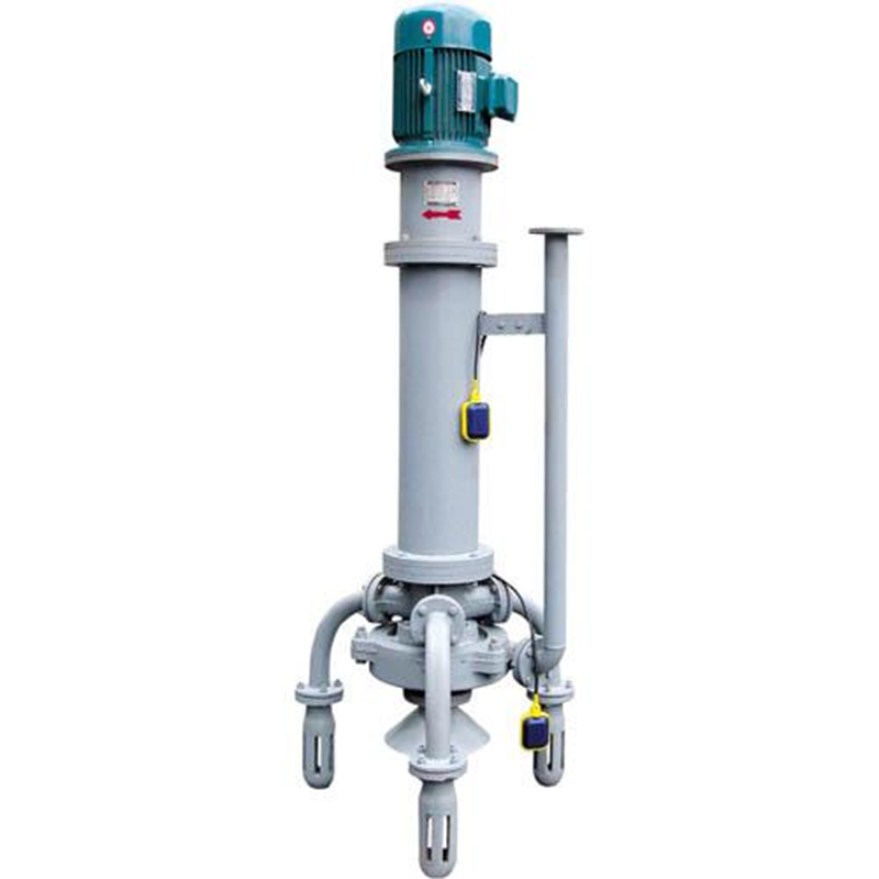
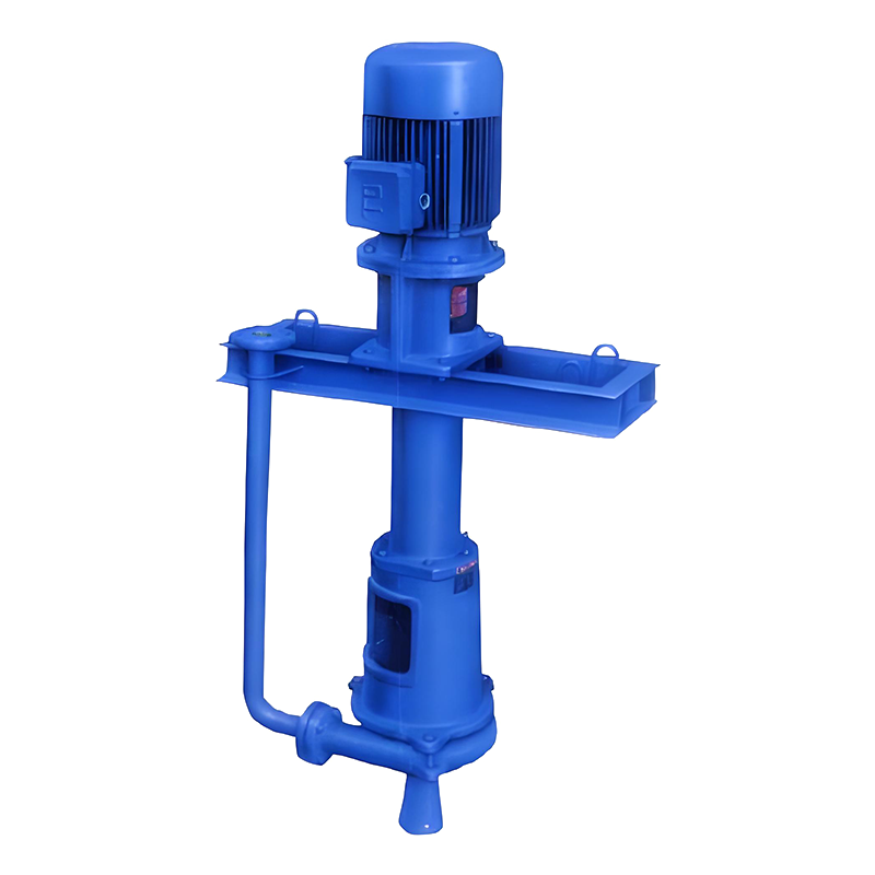
Multi-suction head vertical anti-silt sewage pump
PWDL multi-suction head vertical anti-siltation sewage pump is a new energy-saving product with anti-siltation function. It is ingeniously designed, novel in shape, simple in structure, easy to install, stable in operation, low in noise and high in efficiency. It has been used in different industries and industrial sectors, and has good anti-siltation effect, and is well received by users. Multi-suction head vertical anti-siltation sewage pump is a double-suction centrifugal impurity pump with an open impeller. It allows the solid particle size in sewage to be ≤15mm, with no specific gravity, and the instantaneous maximum allowable concentration is 30-45%. The pump is suitable for industrial production departments such as metallurgy, mining, electricity, coal, papermaking, textile, building materials, machinery, and construction departments as various slurry conveying equipment such as ore slurry, mud, mortar, etc. It can work intermittently or continuously. It is a new type of sewage pump with a wide range of applications and prospects.

- Product model compilation instructions
65PWDL multi-suction sewage pump
65 pump outlet diameter (mm)
PW: sewage
L: vertical pump
2.2 UFQYK float level control device
- 3. Brief introduction of pump structure
3.1 PWDL type
It consists of a vertical motor, motor base, coupling, bearing box, bearing, main shaft, cylindrical bracket, five-way, sleeve, pump cover, impeller, pump casing, main suction head, auxiliary suction head, stirring shaft and stirring wheel. An umbrella-shaped embossed plate is installed at the bottom of the main suction head to prevent the stirring wheel from sucking air into the pump when it is working, affecting the normal operation of the pump.
3.2 PWDL type (upper and lower bearing type)
The bearings of this pump are arranged in an upper and lower manner, but two upper and lower bearing seats are added, and the distance between the two bearings is increased. Therefore, the main shaft has a small swing during operation, which is beneficial to improving the service life of the main shaft.
5.1 Installation sequence
The installation requirements shall be carried out in accordance with the relevant regulations for general mechanical installation. The company shall carry out overall installation and commissioning before leaving the factory. If the user installs it by himself, follow the following installation sequence:
5.1.1 PWDL type sewage pump
5.1.1.1 Install the bearing box and shaft, and adjust the bearing clearance;
5.1.1.2 Install the cylindrical bracket and five-way;
5.1.1.3 Install the pump cover and impeller;
5.1.1.4 Hand-operate the impeller to make the shaft rotate easily;
5.1.1.5 Install the pump housing, main suction head, stirring shaft, stirring wheel, suction elbow, branch suction head, extrusion pipe and pipe fittings. When installing the pipe fittings, screw the threads in place, add a 1.5-2mm thick rubber gasket between each connecting flange, and seal the interface tightly without water leakage;
5.1.1.6 Install the coupling, motor seat, motor and sleeve (leave a 1-2mm gap between the two couplings to prevent the bearing from burning out).
5.1.2.1 Install the upper bearing seat, bearing, shaft and upper gland, and adjust the bearing clearance;
5.1.2.2 Install the lower bearing seat and cylindrical bracket, and fix the lower bearing seat in the cylindrical bracket;
5.1.2.3 Connect the upper bearing seat, lower bearing seat, cylindrical bracket and shaft together;
5.1.2.4 Install the lower bearing, lower gland, mechanical seal and five-way;
5.1.2.5 The following procedures are the same as 1.1.3-1.1.6 of PWDL type sewage pump, but without the sleeve.
5.2 Test run
5.2.1 After the motor is connected to the cable, use a megohmmeter to check the insulation resistance of the motor stator winding to verify whether it meets the requirements;
5.2.2 In order to ensure safe use, the ground wire must be connected;
5.2.3 According to the national standard GB755-65, the motor can only operate normally within the range of ±5% of the power supply voltage;
5.2.4 The motor should be jogged 1-2 times to confirm that the motor rotation direction is correct (it should rotate in the direction of the arrow on the pump body). If it is not correct, the connection position of any two-phase cable should be reversed, and then connected to the pump.
5.2.5 After immersion in water, let the motor run continuously for a few minutes to observe the operating stability of the whole machine, whether there is large vibration, noise and heat, if so, the cause should be found out and the above situation should be eliminated.
5.3 Usage requirements
5.3.1 When the sewage pump is installed and used after being stored for more than half a year, it should be checked first to see if the pump rotates freely. If it is found to be difficult to rotate, it must be repaired before it can be installed and used.
5.3.2 Before the pump is placed in the pump pit, the pump pit must be checked. First, the bottom of the pump pit must be level. Secondly, the debris in the pit, such as iron wire, cement blocks, wooden boards, welding rods and rags, must be cleaned up to prevent damage to the equipment.
5.3.3 During construction, it is not allowed to use the sewage pump as a temporary construction drainage to prevent the new pump from being damaged and affecting the normal operation of production.
5.3.4 When there are two sewage pumps in the same pump pit (one working and the other standby), in order to prevent the standby pump from not working for a long time, causing the pump suction head to be blocked by sediment, which in turn affects the standby pump from starting at any time, the workers should start the standby pump regularly, or the two pumps should be used alternately as working pumps. Make each pump in a working state that can be started at any time.
5.3.5 When the output pipeline is mainly horizontal, a gate valve should be installed on the outlet pipeline, and the motor should be started with the gate valve closed to avoid excessive starting current and burning the motor.
5.3.6 When the output pipeline is mainly vertically lifted, the outlet pipeline can be installed with a gate valve or not (determined by the user). If there is a gate valve, the motor can be started with the gate valve open.
5.3.7 When working intermittently, the pump pit should have sufficient effective adjustment volume so that the maximum number of starts of the sewage pump in one hour does not exceed 6-8 times to avoid burning the motor.
5.3.8 When working intermittently and unmanned, an automatic control device should be installed to start the pump at high water level and stop the pump at low water level.
5.3.9 If used in open air conditions, rain and moisture protection measures should be taken at outdoor switches or wiring terminals to prevent electric shock.
- 4. Wearable parts
The main easily worn and consumable parts include pump cover, pump casing, impeller, agitator wheel and sleeve, which should be inspected and replaced regularly according to actual conditions.
- 5. Causes of failure and solutions
| Fault phenomenon | reason | Elimination method |
|
The motor does not turn |
1. The power supply voltage is too low 2. The three-phase power supply in the cable is missing a phase 3. The power supply is off or the line is faulty 4. Debris is stuck in the mixing wheel or impeller 5. The stator winding is burned out 6. The power lead is too thin or too long, and the voltage drop is too large |
1. Adjust voltage 2. Replace cables 3. Restore power and troubleshoot 4. Remove debris and fix blockages 5. Replace motor 6. Increase wire cross-section |
| The pump flow rate and head decrease or no water is produced | 1. Impeller runs in the opposite direction 2. Pump speed decreases 3. Water level is too shallow or impeller is above the water surface 4. Impeller is worn too much 5. Motor operating conditions are poor, temperature rise is too high or overloaded, thermal protector is activated 6. Sheath wear, air intake |
1. Change the position of any two phases at the three-phase power connector 2. Check the power supply voltage and frequency 3. Reinstall the pump and adjust the water level 4. Replace the impeller 5. After the temperature drops, the protector can automatically reset and operate again. If this happens continuously, the power supply should be cut off to check the cause 6. Replace the sheath |
| Motor stator winding burns out |
1. The pump is out of use, running in a large flow area for a long time, and the protector fails 2. The stator and rotor of the motor are not concentric or the shaft is bent, causing friction between the stator and rotor or the impeller and the pump body |
1. Adjust the use range of the pump and replace the thermal protector 2. Adjust the concentricity, calibrate the shaft or adjust the impeller clearance |
- 6.Application of UFQYK float level control device
In order to ensure the normal and safe operation of the sewage system and extend the service life of the equipment, the pump company launched the float level control device to users.
This control box and the float magnetic switch form a float level control device. It is used for automatic level control of single or multiple sewage pumps.
This device has two working modes: manual and automatic. In the automatic working mode, the sewage pump works according to the position signal of the float switch. The pump stops at low water level and starts at high water level.
This device is equipped with a light display to indicate the operating status. According to special needs, it can also be reserved to send a working status signal to a remote monitoring station so that the centralized monitoring station can monitor the operation of this device.
This device has the function of automatically starting the standby pump. When one pump fails or cannot meet the drainage requirements, the other pump automatically starts working. The standby pump and the working pump can be selected at will.
The installation wiring diagram of the device is shown in Figure
- 7.Installation of magnetic switch (float)
9.1 When a sewage pump is installed in a pump pit, two magnetic switches are installed on the pump (one upper and one lower as shown in the figure). The magnetic switch floats up with the rise of the liquid level in the pit. When it rises to the pump start water level, the pump starts to run. When the water level drops, the other magnetic switch drops to the pump stop water level with the liquid level in the pit, and the pump stops running.
9.2 When two sewage pumps are installed in a pump pit (one working and one standby), one of the working pumps is installed with one magnetic switch on the upper and lower sides, and the other standby pump is only installed on the upper side of the pump, and the floating position of the magnetic switch must be 100-150mm higher than the floating position of the working pump magnetic switch.
9.3 The magnetic switch is installed and fixed on the bracket reserved for the sewage pump. The length of the wire on the switch from the fixed position is adjusted according to the pump stop and pump start water levels. The pump stop water level is not less than 280mm from the bottom of the pit. The pump start water level is 100-150mm from the floor of the pit.
9.4 Generally, the magnetic switch wires do not need to be connected to a terminal box separately. They can be directly connected to the wiring terminals in the control box. For details on the connection between the motor, magnetic switch and control box on the pump, please refer to the electrical schematic diagram and wiring diagram delivered with the machine.
- Performance Parameters
| model | flow | Lift | Speed | Required NPSH |
efficiency (%) |
Shaft power (kw) |
Matching motor |
weight
(kg) |
|
||
|
(kw) |
Specification
|
||||||||||
|
Inhalation Inlet |
|
||||||||||
|
50PWDL |
15.3 22.5 34.2 |
8.7 7.5 1.8 |
1470 |
|
34.9 38.6 31.2 |
1.0 1.2 1.5 |
3 |
Y100L2-4B5 |
250 |
|
50 |
|
50PWDL |
9.9 14.4 21.6 |
3.5 3.0 1.9 |
910 |
|
34.9 38.6 31.2 |
0.3 0.3 0.3 |
1.1 |
Y90L-6B5 |
250 |
|
50 |
|
65PWDL |
38 58 98 |
34.7 31.9 26.0 |
1470 |
|
43.7 51.9 51.7 |
8.2 9.7 13.4 |
18.5 |
Y180M-4V1 |
530 |
|
65 |
|
65PWDL |
25 38 64 |
14.8 13.6 11.1 |
960 |
|
43.7 51.9 51.7 |
2.3 2.7 3.7 |
5.5 |
Y132M2-6B5 |
530 |
|
65 |
|
65PWDL |
34 52 88 |
28.1 25.8 21.0 |
1470 |
|
43.7 51.9 51.7 |
6.0 7.1 9.8 |
15 |
Y160-4V1 |
530 |
|
65 |
|
65PWDL |
23 34 58 |
12.0 11.0 9.0 |
960 |
|
43.7 51.9 51.7 |
1.7 2.0 2.7 |
4.0 |
Y132M1-6B5 |
530 |
|
65 |
|
80PWDL |
105 144 201 |
45.5 41.4 32.5 |
1480 |
|
52.1 58.2 54.2 |
25.0 27.9 32.8 |
45 |
Y225M-4V1 |
660 |
|
80 |
|
80PWDL |
69 94 132 |
19.5 17.8 14.0 |
970 |
|
52.1 58.2 54.2 |
7.0 7.8 9.3 |
15 |
Y180L-6V1 |
660 |
|
80 |
|
80PWDL |
50 72 |
40 38 |
1480 |
|
52.1 58.2 54.2 |
19.3 21.5 25.3 |
22 |
Y225S-4V1 |
660 |
|
80 |
|
80PWDL |
63 86 121 |
16.4 15.0 11.8 |
970 |
|
52.1 58.2 54.2 |
5.4 6.0 7.2 |
11 |
Y160-6V1 |
660 |
|
80 |
|
100PWDL |
157 214 293 |
36.8 32.6 24.4 |
1480 |
|
60.2 65.1 58.2 |
26.1 29.2 33.5 |
45 |
Y225M-4V1 |
850 |
|
100 |
|
100PWDL |
103 140 192 |
15.8 14.0 10.5 |
970 |
|
60.2 65.1 58.2 |
7.4 8.2 9.4 |
15 |
Y180L-6V1 |
850 |
|
100 |
|
100PWDL |
143 195 267 |
30.6 27.1 20.3 |
1480 |
|
60.2 65.1 58.2 |
19.8 22.1 25.4 |
37 |
Y225S-4V1 |
850 |
|
100 |
|
100PWDL |
94 128 175 |
13.1 11.6 8.7 |
970 |
|
60.2 65.1 58.2 |
5.6 6.2 7.1 |
11 |
Y160L-6V1 |
850 |
|
100 |
|
150PWDL |
198 332 364 |
17.9 13.2 12.1 |
980 |
|
63.1 68.1 66.8 |
15.3 17.5 18.0 |
37 |
Y250M-6V1 |
900 |
|
150 |
|
150PWDL |
147 247 271 |
10.0 7.3 6.7 |
730 |
|
63.1 68.1 66.8 |
6.3 7.2 7.4 |
15 |
Y200L-8V1 |
900 |
|
150 |
|
150PWDL |
119 200 219 |
6.5 4.8 4.4 |
590 |
|
63.1 68.1 66.8 |
3.3 3.8 3.9 |
11 |
Y160L-6B3 |
900 |
|
150 |
|
150PWDL |
181 304 332 |
15.0 11.0 10.1 |
980 |
|
63.1 69.1 66.8 |
11.7 13.4 13.8 |
22 |
Y200L2-6V1 |
900 |
|
150 |
|
150PWDL |
134 226 248 |
8.4 6.1 5.6 |
730 |
|
63.1 68.1 66.8 |
4.8 5.5 5.7 |
11 |
Y180L-8V1 |
900 |
|
150 |
|
150PWDL |
109 183 200 |
5.4 4.0 3.7 |
590 |
|
63.1 68.1 66.8 |
2.5 2.9 3.0 |
7.5 |
Y160M-6B5 |
900 |
|
150 |
|
TYPE |
|
Head H (m) |
Speed n (r/min) |
NPSHr (m) |
Effici ency η (%) |
Shaft Power P (kw) |
Matingmotor |
Weight (kg) |
|
|
||
|
Power (kw) |
Specif |
|||||||||||
|
Inlet |
Outlet |
|||||||||||
|
40PWDL |
7.56 14.76 18.00 |
5.5 5 4 |
1000 |
|
30 38 35 |
0.38 0.53 0.56 |
1.1 |
Y90S-4 |
285
300 |
960×500×2013 |
81 |
40 |
|
40PWDL |
9.00 17.64 24.12 |
8.2 7 6 |
1200 |
|
30 38 35 |
0.67 0.88 1.10 |
1.1
1.5 |
Y90S-4
Y90L-4 |
285
300 |
960×500×2013 |
81 |
40 |
|
40PWDL |
10.08 20.52 27.72 |
11 9 8 |
1400 |
|
30 38 35 |
1.00 1.3 1.7 |
2.2
3 |
Y100L1-4
Y100L2-4 |
285
300 |
960×500×2013 |
81 |
40 |
|
40PWDL |
10.44 20.88 28.08 |
11.5 9.5 8.5 |
1420 |
|
30 38 35 |
1.1 1.4 1.8 |
2.2
3 |
Y100L1-4
Y100L2-4 |
285
300 |
960×500×2013 |
81 |
40 |
|
40PWDL |
11.16 21.96 29.52 |
12.5 10.6 9 |
1500 |
|
30 38 35 |
1.27 1.7 2.1 |
3
4 |
Y100L1-4
Y112M-4 |
285
300 |
960×500×2013 |
81 |
40 |
|
40PWDL |
11.88 23.40 30.96 |
14.5 12.5 10.5 |
1600 |
|
30 38 35 |
1.56 2.1 2.5 |
3
4 |
Y100L2-4
Y112M-4 |
285
300 |
960×500×2013 |
81 |
40 |
|
40PWDL |
12.60 24.84 26.64 |
16.5 14 11.5 |
1700 |
|
30 38 35 |
2.1 2.5 2.8 |
4
5.5 |
Y112M-4
Y132S-4 |
285
300 |
960×500×2013 |
81 |
40 |
|
40PWDL |
12.96 26.64 35.28 |
18.5 15.5 13 |
1800 |
|
30 38 35 |
2.2 2.9 3.6 |
4
5.5 |
Y112M-2
Y132S1-2 |
285
300 |
960×500×2013 |
81 |
40 |
|
40PWDL |
14.04 27.72 37.80 |
20.5 17.5 15 |
1900 |
|
30 38 35 |
2.6 3.5 4.4 |
5.5
7.5 |
Y132S1-2
Y132S2-2 |
285
300 |
960×500×2013 |
81 |
40 |
|
40PWDL |
14.4 29.16 39.24 |
22.5 19.5 16.5 |
2000 |
|
30 38 35 |
2.9 4.1 5.03 |
5.5
7.5 |
Y132S1-2
Y132S2-2 |
285
300 |
960×500×2013 |
81 |
40 |
|
40PWDL |
15.48 30.60 41.40 |
25 21.5 18.5 |
2100 |
|
30 38 35 |
3.5 4.7 6 |
7.5
11 |
Y132S2-2
Y160M1-2 |
285
300 |
960×500×2013 |
81 |
40 |
|
40PWDL |
16.20 32.4 43.92 |
27 23.5 20 |
2200 |
|
30 38 35 |
4 5.5 6.8 |
7.5
11 |
Y132S2-2
Y160M1-2 |
285 300 |
960×500×2013 |
81 |
40 |
|
65PWDL |
19.08 44.64 48.6 |
6.8 5.9 5.1 |
700 |
|
40 51 50 |
0.88 1.4 1.35 |
3 |
Y132S-6 |
432
500 |
1193×680×2590 |
104 |
65 |
|
65PWDL |
19.8 41.4 49.68 |
7 6 5.4 |
710 |
|
40 51 50 |
0.96 1.3 1.5 |
2.2
3 |
Y132S-8B5
Y132M-8B5 |
432
500 |
1193×680×2590 |
104 |
65 |
|
65PWDL |
21.6 46.08 55.58 |
8.8 7.4 6.8 |
800 |
|
40 51 50 |
1.3 1.8 2.1 |
3
4 |
Y132S-6
Y132M1-6 |
432
500 |
1193×680×2590 |
104 |
65 |
|
65PWDL |
24.84 52.2 61.56 |
11 9.4 8.5 |
900 |
|
40 51 50 |
1.8 2.6 2.85 |
4
5.5 |
Y132M1-6
Y132M2-6 |
432
500 |
1193×680×2590 |
104 |
65 |
|
65PWDL |
26.64 55.8 65.52 |
12.5 10.5 9.5 |
960 |
|
40 51 50 |
2 3.1 3.4 |
4 5.5 7.5 |
Y132M1-6B5 Y132M2-6B5 Y160M-6B5 |
285
300 |
1193×680×2590 |
104 |
65 |
|
65PWDL |
29.52 63.36 75.60 |
16.5 13.7 12.5 |
1100 |
|
45 51 50 |
2.9 4.6 5.1 |
7.5
11 |
Y132M-4
Y160M-4 |
432
500 |
1193×680×2590 |
104 |
65 |
|
65PWDL |
32.4 69.84 82.08 |
19.5 16.4 15 |
1200 |
|
45 51 50 |
3.8 6.1 6.7 |
7.5 11 15 |
Y132M-4 Y160M-4 Y160L-4 |
432
500 |
1193×680×2590 |
104 |
65 |
|
65PWDL |
45 75.24 88.2 |
22.5 19.4 17.7 |
1300 |
|
45 51 50 |
6.1 7.8 8.5 |
11
15 |
Y160M-4
Y160L-4 |
432
500 |
1193×680×2590 |
104 |
65 |
|
TYPE |
|
Head H (m) |
Speed n (r/min) |
NPSHr (m) |
Effici ency η (%) |
Shaft Power P (kw) |
Matingmotor |
Weight (kg) |
|
|
||
|
Power (kw) |
Specif |
|||||||||||
|
Inlet |
Outlet |
|||||||||||
|
65PWDL |
48.6 81 95.4 |
25.5 22.4 20.5 |
1400 |
|
45 51 50 |
7.5 9.7 10.7 |
11 15 18.5 |
Y160M-4 Y160L-4 Y180M-4 |
432
500 |
1193×680×2590 |
104 |
65 |
|
65PWDL |
50.76 84.6 100.08 |
28.3 24.5 22.5 |
1470 |
|
45 51 50 |
8.7 11.1 12.3 |
18.5
22 |
Y180M-4B5
180L-4B5 |
432
500 |
1193×680×2590 |
104 |
65 |
|
65PWDL |
52.2 86.4 106.2 |
29.5 25.5 23.5 |
1500 |
|
45 51 50 |
9.3 11.8 13.6 |
15 18.5 22 |
Y160L-4 Y180M-4 Y180L-4 |
432
500 |
1193×680×2590 |
104 |
65 |
|
100PWDL |
41.4 90 111.6 |
6.3 5.5 5 |
500 |
|
40 55 56 |
1.8 2.4 2.7 |
3 4 5.5 |
Y132M-8 Y160M1-8 Y160M2-8 |
867
920 |
1558×870×3303 |
175 |
100 |
|
100PWDL |
43.2 104.4 133.2 |
9 8.1 7.5 |
600 |
|
40 55 56 |
2.7 4.2 4.8 |
5.5 7.5 11 |
Y160M2-8 Y160L-8 Y180L-8 |
867
920 |
1558×870×3303 |
175 |
100 |
|
100PWDL |
57.6 124.2 154.8 |
12.2 11 10.2 |
700 |
|
40 55 56 |
4.8 6.7 7.7 |
11
15 |
Y160L-6
Y180L-6 |
867
920 |
1558×870×3303 |
175 |
100 |
|
100PWDL |
61.2 129.6 162 |
13.4 12 11.2 |
730 |
|
40 55 56 |
5.6 7.7 8.8 |
11 15 18.5 |
Y180L-8B5 Y200L-8B5 Y225S-8B5 |
867
920 |
1558×870×3303 |
175 |
100 |
|
100PWDL |
64.8 142.2 174.6 |
16 14.4 13.3 |
800 |
|
40 55 56 |
7 10.1 11.3 |
15
18.5 |
Y160L-6
Y200L1-6 |
867
920 |
1558×870×3303 |
175 |
100 |
|
100PWDL |
68.4 151.2 187.2 |
18 16.4 15 |
850 |
|
40 55 56 |
8.4 12.3 13.6 |
15 18.5 22 |
Y160L-6 Y200L1-6 Y200L2-6 |
867
920 |
1558×870×3303 |
175 |
100 |
|
100PWDL |
75.6 160.2 194.4 |
20.3 18 16.7 |
900 |
|
40 55 56 |
10.4 14.3 15.8 |
18.5 22 30 |
Y200L1-6 Y200L2-6 Y225M-6 |
867
920 |
1558×870×3303 |
175 |
100 |
|
100PWDL |
81 174.6 214.2 |
23.8 21.5 20 |
980 |
|
40 55 56 |
13 18.6 20.8 |
22 30 37 |
Y220L2-6 Y225M-6 Y250M-6 |
867
920 |
1558×870×3303 |
175 |
100 |
|
100PWDL |
82.8 176.4 217.44 |
25 22.5 20.7 |
1000 |
|
40 55 56 |
14.1 19.6 21.9 |
22 30 37 |
Y180L-4 Y220L-4 Y225S-4 |
867
920 |
1558×870×3303 |
175 |
100 |
|
100PWDL |
86.4 185.4 230.4 |
27.5 24.5 22.5 |
1050 |
|
40 55 56 |
16.2 22.5 25.2 |
30 37 45 |
Y200L-4 Y225S-4 Y225M-4 |
867
920 |
1558×870×3303 |
175 |
100 |
|
100PWDL |
90 194.4 240.48 |
30.3 27 25 |
1100 |
|
40 55 56 |
18.5 25.9 29.2 |
30 37 45 |
Y200L-4 Y225S-4 Y225M-4 |
867
920 |
1558×870×3303 |
175 |
100 |
|
100PWDL |
97.2 205.2 243 |
33 29.5 27.4 |
1150 |
|
40 55 56 |
21.8 29.9 33.3 |
30
45 |
Y200L-4
Y225M-4 |
867
920 |
1558×870×3303 |
175 |
100 |
|
100PWDL |
100.8 212.4 262.8 |
35.8 32.1 29.5 |
1200 |
|
40 55 56 |
24.5 33.7 37.7 |
37
45 |
Y225S-4
Y225M-4 |
867
920 |
1558×870×3303 |
175 |
100 |
|
150PWDL |
118.8 208.8 288 |
8.1 8 6.5 |
500 |
|
45 53 53 |
6.4 8.5 9.6 |
11
15 |
Y180L-8
Y200L-8 |
1737
1850 |
1870×1100×3986 |
|
150 |
|
150PWDL |
133.2 223.2 316.8 |
10.6 9.6 8 |
550 |
|
45 53 53 |
8.5 11 13 |
15 18.5 22 |
Y200L-8 Y225S-8 Y225M-8 |
1737
1850 |
1870×1100×3986 |
|
150 |
|
150PWDL |
140.4 244.8 342 |
12.7 11.4 9.7 |
600 |
|
45 53 53 |
10.8 14.3 17 |
22
30 |
Y225M-8
Y250M-8 |
1737
1850 |
1870×1100×3986 |
|
150 |
|
150PWDL |
154.8 270 367.2 |
15 13.4 11.4 |
650 |
|
45 53 53 |
13.7 18.6 21.5 |
22 30 37 |
Y225M-8 Y250M-8 Y280S-8 |
1737
1850 |
1870×1100×3986 |
|
150 |
Cooperation Process
Requirement Communication
- After initial contact, the client manager will conduct a detailed needs analysis, collecting information on pump usage environment, flow rate, pressure, etc. The technical team will then develop a preliminary solution and provide detailed product information and recommendations.
Technical Selection
- After detailed product recommendations and technical consultations, the client confirms the selection. We will provide a quotation and contract to ensure that technical and business terms are clear.
Workshop Production
- After signing the contract, we will formulate and execute a production plan to ensure product quality and progress, while the client can track the production status in real-time.
Factory Testing
- Upon completion of production, we conduct comprehensive quality testing and provide detailed test reports and certificates to ensure the products meet standards and client requirements.
Installation and Commissioning
- We offer on-site installation, commissioning, and training services to ensure optimal pump performance and that clients can operate and maintain the equipment correctly.
After-Sales Support
- We provide 24-hour customer service and maintenance and warranty services to ensure timely resolution of issues, and regularly inspect equipment to maintain long-term stable operation.
Continuous Improvement
- Collect customer feedback to continuously optimize product and service quality. We adapt to market changes and client needs by continually improving and upgrading products to maintain industry leadership.
Client Service
and Technical Support
Customer Support
We provide 24-hour hotline and online support to ensure that customers receive timely technical support and problem solutions via phone, email, or online platforms.
After-Sales Service Description
We provide technical support and local repair advice to help customers resolve issues encountered with product use.
Technical Consultation
We offer detailed product manuals and technical documentation, and assist customers in resolving technical issues through remote diagnostics and technical guidance.
Quality Assurance
We provide technical support and maintenance advice to help customers address faults caused by product quality issues and offer appropriate solutions based on fault information and purchase proof.
After-Sales Assurance
We offer warranty services to ensure repair or replacement of products with quality issues during the warranty period and encourage customers to provide feedback to help us improve products and services.
Service Commitment
We commit to responding to customer issues within 24 hours and continuously improving service processes and measures to ensure the best customer experience.

Contact Us